MECHANICAL SEAL VAPOUR PRESSURE CONTROL USING API PIPING PLANS
- Specialised Flow Solutions

- Mar 10, 2023
- 3 min read
Updated: Jun 28, 2025
Maintaining a stable seal chamber environment is critical for mechanical seal performance. One of the most important factors is ensuring a sufficient vapour pressure margin—the difference between the absolute pressure in the seal chamber and the absolute vapour pressure of the process fluid at the local operating temperature.
If this margin is too small, flashing may occur within the fluid film between seal faces, leading to dry running, increased heat, and premature mechanical seal failure.
What Is Vapour Pressure Margin in Mechanical Sealing?
The vapour pressure margin is defined as:
Seal chamber absolute pressure – Process fluid absolute vapour pressure
A sufficient margin prevents fluid flashing and supports a stable lubricating film at the seal interface.
The API 682 4th Edition standard recommends:
A minimum vapour pressure margin of 50 psi, or
A minimum ratio of 3:1 (seal chamber pressure : fluid vapour pressure), when 50 psi can’t be achieved.
Why Not Use a Heat Exchanger?
Cooling the process fluid with a heat exchanger is the API-preferred method to reduce vapour pressure. However, in many applications, cooling is either:
Impractical due to system constraints
Too costly or complex to implement
Fortunately, mechanical seal piping plans can provide a reliable alternative by controlling pressure and flow within the pump to optimise conditions around the seal.
Piping Plans That Improve Vapour Pressure Margins
The most common piping plans used to manage seal chamber pressure without a heat exchanger are API Plan 11 and API Plan 14. These plans are highly effective in improving sealing reliability by:
Increasing the seal chamber pressure
Managing seal face heat
Supporting fluid film stability
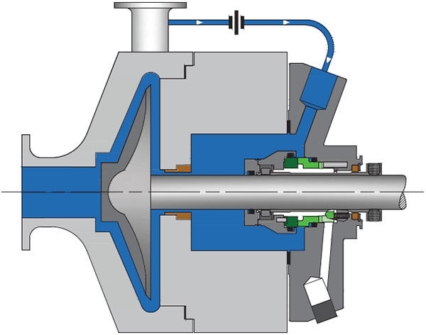
API Plan 11 – Recirculation from Pump Discharge
Plan 11 is the most commonly used flush plan for single mechanical seals.
Features:
Recirculates process fluid from a higher-pressure region (e.g., pump discharge) to the seal chamber
Flushes away face-generated heat
Maintains pressure above vapour pressure to prevent flashing
Commonly used with horizontal multistage pumps and throat bushings/orifices to control flow

API Plan 14 – Recirculation with Suction Return
Plan 14 combines Plan 11 and Plan 13 to further stabilise pressure and temperature.
Features:
Recirculation from discharge to seal chamber, and from seal chamber to suction
Flushes and vents the seal environment
Throat bushing helps isolate the seal chamber
Maintains continuous circulation to stabilise operating conditions
Both plans utilise pressure distribution within the pump and system to optimise the seal chamber environment without the need for additional external equipment.
Factors That Impact Seal Chamber Conditions
To effectively use piping plans like Plan 11 and Plan 14, consider how these pump design factors influence seal chamber pressure and flow:
Seal chamber bore configuration
Number of impeller stages
Presence of balance lines
Throat bushing clearance and design
A poorly selected flush plan can harm seal performance just as much as a well-designed one can improve it.
Seal Face Heat Management Without External Cooling
According to API 682, face-generated heat should not raise seal chamber temperature by more than 10°F (≈12.2°C). Proper piping plans manage this heat by ensuring adequate flow through the chamber, helping to:
Maintain the fluid film between seal faces
Avoid dry running conditions
Prevent thermal degradation of seal components
Why Vapour Pressure Margin Matters
At the heart of all mechanical sealing solutions is the need to control the fluid film between the seal faces. Vapour pressure margin plays a key role in keeping this film intact.
By carefully selecting and configuring piping plans based on process fluid properties, system layout, and pressure profiles, mechanical seal life and reliability can be significantly improved—without the need for a heat exchanger.

Choose the Right Mechanical Seal Piping Plan for Mechanical Seal Vapour Pressure Control
While API Plans 11 and 14 are the most common strategies to improve mechanical seal vapour pressure control, many other options exist. For a full breakdown of API flush plans and their sealing benefits, consult Flexaseal’s Piping Plan Guide.
Specialised Flow Solutions is the exclusive Australian distributor of Flexaseal Engineered Seals and Systems, a leading U.S. manufacturer of high-performance mechanical seals, metal bellows, and split cartridge seals. We provide expert technical support and help our clients across Australia solve the most demanding sealing challenges.
Need help selecting the right piping plan or mechanical seal? Contact the team at Specialised Flow Solutions at sales@specialised-sfs.com.au for expert advice on pump sealing systems.


Comments